
NRF24L01 comunicación de dos arduino por radiofrecuencia Geek Factory
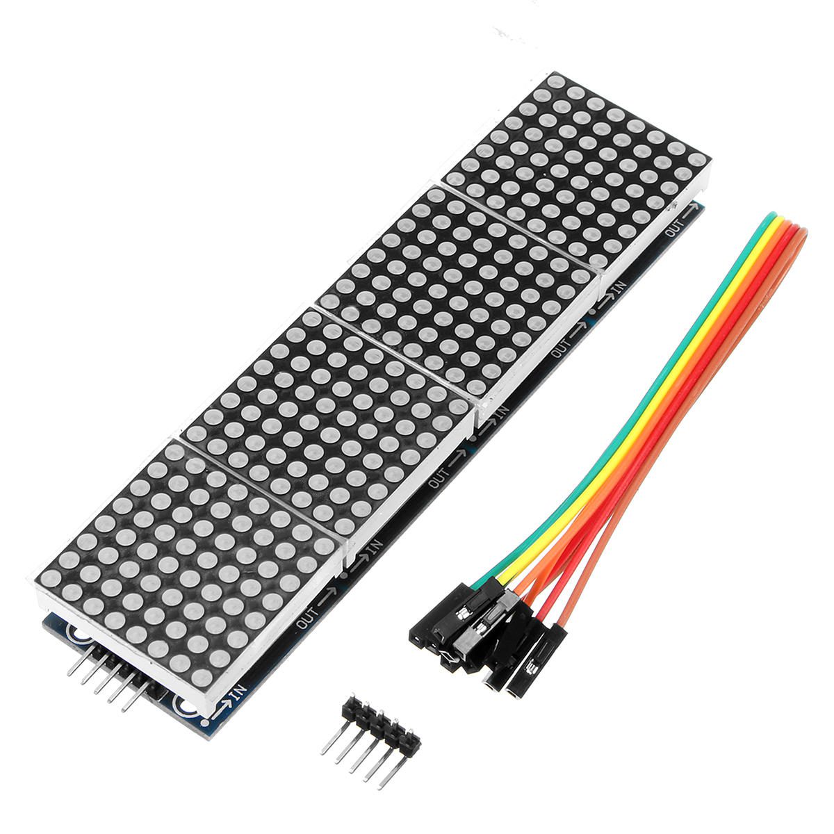
MAX7219 LED dot matrix display specifications How to connect the dot matrix display to the Arduino Hardware SPI pin locations MAX7219 LED dot matrix display connections Power requirements Installing the MD_Parola and MD_MAX72XX Arduino libraries Different types of LED dot matrix displays FC-16 8×8 or 8×32 module Module orientation and connections
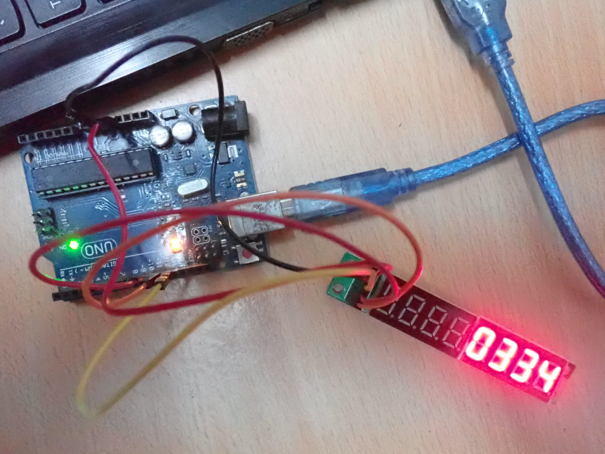
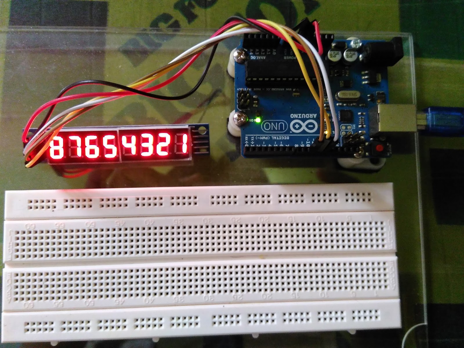
Arduino compatible coding 10 Sevensegment multiplexing using Arduino
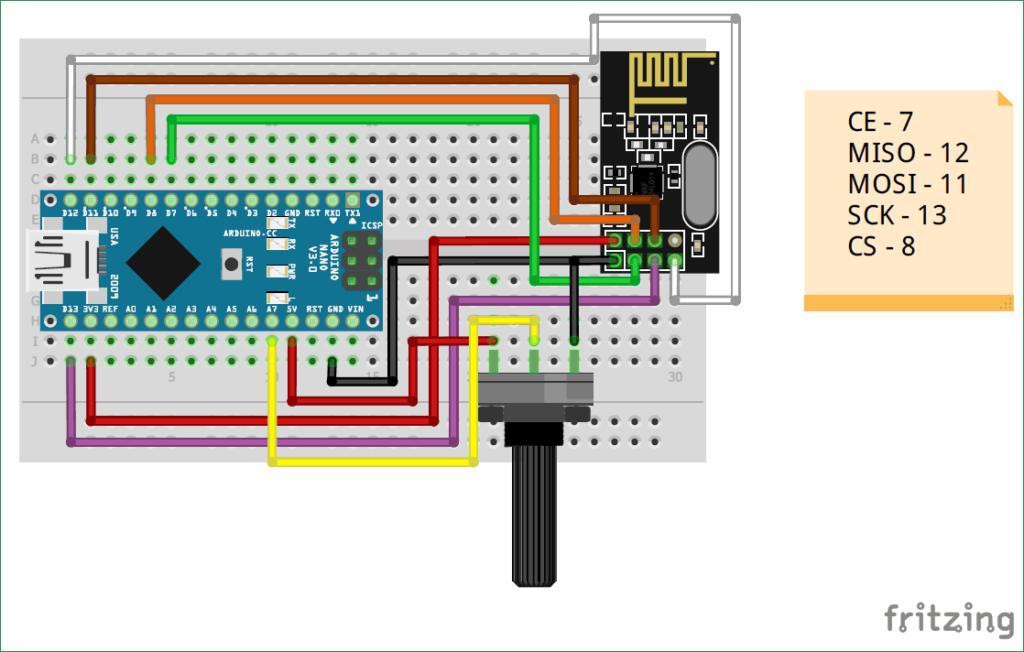
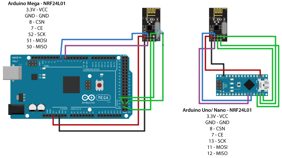
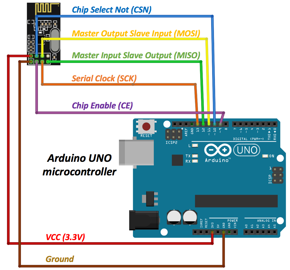
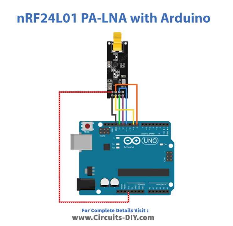
Connect power pins from NRF24L01 to the Arduino as shown below: NRF24L01 ARDUINO VCC 3.3V GND GND CE and CSN pins can be connected to any digital pins. Then in RF24 library, you can specify which pins you used. I chose pins 7 and 8 because I will use them in the examples. On Arduino UNO boards SPI pins are connected with some digital pins.

Arduino compatible coding 10 Sevensegment multiplexing using Arduino
The nRF24L01 module is very popular choice for wireless communication when using Arduino. I have already used this module for numerous Arduino projects and you can check out some of them here: DIY Arduino RC Transmitter Arduino RC Airplane | 100% DIY DIY Arduino based RC Hovercraft Arduino Wireless Weather Station Project

ARDUINO to MAX7219 LED Matrix display (Easy guide setup, WIRING
NRF24L01 is a single-chip transceiver module that uses the SPI protocol or an RF24 library. Here is all that you need to know about NRF24L01, how it works, NRF24L01 Arduino Guide, and NRF24L01 Module Pinout.. The transceiver module consists of fully integrated frequency synthesizers, a crystal oscillator, an amplifier, a demodulator, a modulator, and an Enhanced ShockBurst protocol engine.

NRF24L01 & Arduino Wireless DHT11 Temperature Monitor
Gromo is a principal village in the commune of Bergamo with several walking paths that lead to the renowned Parco delle Orobie Bergamasche, a protected natural park of 70,000ha (700sqkm) at the foot of the Alps that border Switzerland. The village architecture is characterised by grey stone with black slate roofs, and at its centre is Piazza Dante, which has original frescoes from the 13th.
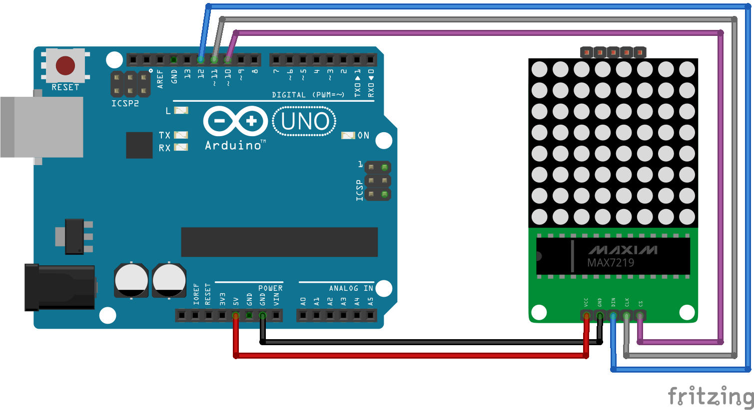
Arduinoer Arduino Uno + MAX7219 8x8 LED Matrix via SPI, using
The module has the generic nRF24L01 IC from Nordic semi-conductors which is responsible for transmission and reception of data. The IC communicates using the SPI protocol and hence can be easily interfaced with any microcontrollers. It gets a lot easier with Arduino since the libraries are readily available. The pinouts of a standard nRF24L01.
CARA MEMPROGRAM 8 DIGIT 7 SEGMENT MENGGUNAKAN SPI MAX7219 DENGAN
Max7219 can be powered from 5V of Arduino. I did a project where 4 Max7219 were powered. With 9V into the barrel jack the 5V regulator would overheat after a while. With 7.5V things ran smoother.
Interface nRF24L01 com Arduino servo motor de controle Cap Sistema
Recent usage in crossword puzzles: LA Times - Dec. 23, 2018; LA Times - April 1, 2016; LA Times - Oct. 16, 2015; Chronicle of Higher Education - Dec. 9, 2011
How nRF24L01+ Wireless Module Works and Interfaces with Arduino Open
The MAX7219 communicates via the SPI interface, so it only needs 3 data pins to connect to a microcontroller. In addition, we can daisy-chain multiple modules together for a larger display using the same 3 wires. Setting Maximum Current and Brightness
Makerobot Education nRF24L01 Interfacing with Arduino UNO
In this tutorial we will learn how to build an Arduino wireless network, composed of multiple NR24L01 transceiver modules. You can watch the following video or read the written tutorial below. Overview
Cara Menghubungkan Nrf24l01 Dengan Arduino Untuk Komunikasi Wireless Images
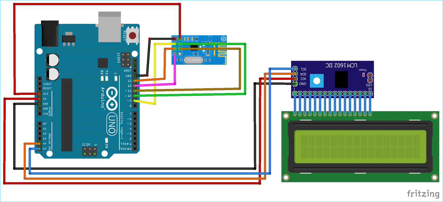
The transmitter side consists of an Arduino UNO, nRF24L01 module, and DHT11 sensor. Interfacing of the Arduino UNO with nRF24L01 and DHT11 is shown below. Arduino continuously gets data from the DHT11 sensor and sends it to the nRF24L01 Transmitter. Then the nRF transmitter transmits the data into the environment. nRF24L01. Arduino Uno. VCC. 3.3V.
Gallery NRF24L01 testing circuit using Arduino Hackaday.io
The nRF24L01+ module is designed to operate in the 2.4 GHz worldwide ISM frequency band and uses GFSK modulation for data transmission. The data transfer rate is configurable and can be set to 250kbps, 1Mbps, or 2Mbps.

NRF24L01 Wireless Communication Arduino based transmitter Remote
Works started on Sanpellegrino's "Factory of the Future", designed by BIG-Bjarke Ingels Group on the brand's 120 th year anniversary. Scheduled to open in 2022, the new production plant.
nRF24L01 Wireless RF Transceiver Module Working & Interface with
* We use pins 6,5 and 4 on the Arduino for the SPI interface * Pin 6 is connected to the DATA IN-pin of the first MAX7221 * Pin 5 is connected to the CLK-pin of the first MAX7221 * Pin 4 is connected to the LOAD (/CS)-pin of the first MAX7221 */ LedControl lc1=LedControl (6,5,4,2); unsigned long delaytime=500; void setup () { //wake up the.
Interfacing Nrf24l01 With Arduino Uno Wireless Communication Arduino
When I straight connect the NRF24L01 to SPI1 it doesn't work. After some research it appears as if it's not written for boards that have more than one SPI bus. I found a workaround by changing the code in pins_arduino.h to the following - essentially commenting out the original #defines for PIN_SPI_MISO, etc. and changing to the SPI1 pins.
CONTROL LED MATRIX MAX7219 WITH ARDUINO Visuino Visual Development
RF24 makes use of the standard hardware SPI pins (MISO, MOSI, SCK) and requires two additional pins, to control the chip-select and chip-enable functions. RF24 radio (ce_pin, cs_pin); These pins must be chosen and designated by the user and can use any available pins. Alternate SPI Support